Quantum-O · Chipset

A naturally quiet, fault-tolerant processor on one die.

Quantum computing has been held back by two physical constraints: decoherence destroys qubit states, and interconnect noise poisons gate operations. Quantum-O v1.0 eliminates both — SiV spin qubits in isotopically-purified ²⁸Si, non-Abelian Majorana boundary shielding, on-die Cryo-CMOS control, and Si₃N₄ photonic interconnects bonded into a single monolithic package.
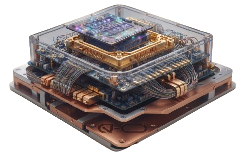
Quantum-O v1.0 fully assembled processor stack
T₂ coherence
2.4 s
uncorrected, ²⁸Si
Logical error
< 10⁻⁶
Majorana braided
Gate energy
< 0.5 µW
per cryo-CMOS gate
Interconnect
738 nm
Si₃N₄ micro-ring
Architecture

Four bonded layers. One monolithic die.

Reading the die top-down, from the cryogenic optical fabric through the topological shield to the ²⁸Si spin core.

Annotated cross-section of the Quantum-O v1.0 chipset — processor stack, qubit array, photonic layer, cryogenic driver, thermal interface
Fig. A · Annotated cross-section — Q-O v1.0 monolithic stack
Exploded view of the four bonded layers of the Quantum-O v1.0 chipset
LAYER 04
Photonic Waveguide Network (Si₃N₄)
738 nm micro-ring resonators bind SiV emission into flying photonic qubits and route entanglement across the die array.
LAYER 03
Cryo-CMOS Control (4 K)
Integrated microwave pulse generators, readout amplifiers and DC bias execute gates below 0.5 µW — line length drops from metres to micrometres, keeping thermal load off the sub-Kelvin core.
LAYER 02
Topological Shielding — Majorana boundaries
Non-Abelian zero-mode tracking lines simulate anyon braiding, holding logical error rates below 10⁻⁶.
LAYER 01
Active Quantum Core (15 mK, ²⁸Si substrate)
Isotopically-purified silicon (99.9999% ²⁸Si) hosts SiV colour centres in deterministic diamond nanostructures on a hexagonal lattice. Eliminating the ambient nuclear-spin bath pushes T₂ beyond 1.2 s.
Comparison

Why the monolithic path wins.

ModalityT₂InterconnectFault tolerance
Superconducting~100 µscoax bundlessurface-code QEC
Trapped ion> 10 sfree-space opticssurface-code QEC
Photonic (LOQC)n/a (flying)off-chip waveguidesprobabilistic / KLM
Neutral atom~1–10 soptical tweezerssurface-code QEC
Quantum-O v1.02.4 son-die Si₃N₄ 738 nmMajorana-braided (< 10⁻⁶)
Core innovations

Six breakthroughs. One monolith.

Every element of the Q-O v1.0 stack is a defensible engineering claim — the combination is what makes the architecture new.

INV-01
Spin-Topological Hybrid

First monolithic integration of spin-based and topological qubit architectures on a single die — combining the coherence of SiV colour centres with Majorana-mode fault tolerance.

INV-02
Majorana QEC Layer

Non-Abelian anyon braiding projects topological shielding boundaries around each spin-qubit cluster, delivering hardware-level error correction without full surface-code overhead.

INV-03
Photonic Interconnect

A Si₃N₄ waveguide network replaces metallic trace routing. Micro-ring resonators map spin states into flying photonic qubits at 738 nm, distributing entanglement without galvanic contacts.

INV-04
Integrated Cryo-CMOS

Control electronics built into the die at 4 K collapse microwave line lengths from metres to micrometres, eliminating the coaxial-cable bottleneck that limits every competing architecture.

INV-05
Pure-Optical CZ Gate

A photon-mediated controlled-phase gate targets 99.92% fidelity using Gaussian-derivative pulse shaping (GDPE) — no noisy microwave bus between qubit pairs.

INV-06
²⁸Si Isotopic Substrate

Isotopically-purified Silicon-28 (99.9999%) removes the ambient nuclear-spin bath — the dominant dephasing mechanism — extending uncorrected T₂ to 2.4 s.

Live telemetry

Instrument panel — 32-node qubit matrix.

A simulated sub-Kelvin readout of the Quantum-O v1.0 core, sampled every 1.8 s.

● QPU ONLINEtier 1 · 0.0150 K · tier 2 · 4.0000 K
FIDELITY
99.92%
GATE
GDPE / CZ
NODE ACTIVE
--
System consoletail -f /var/log/qo.log
[00:00:00] SYSTEM BOOT — Quantum-O v1.0 cores online.
[00:00:01] Cryo-stack thermalised. Tier 1 substrate stable.
Statutory utility patent · US 2024/XXXXXXX A1

The patent series, one sheet at a time.

Nine sheets covering the monolithic dual-layer hybrid spin-topological QPU with integrated cryo-CMOS and Si₃N₄ photonic waveguide interconnects.

Sheet 1 · Title, inventor & abstractPCT/USPTO formal utility patent application — Quantum-O Chipset: a monolithic dual-layer hybrid spin-topological QPU with integrated Cryo-CMOS control and on-chip Si₃N₄ photonic waveguide routing. Inventor: Fabian Jean-Baptiste. Assignee: Quantum Operations LLC.
Technical whitepaper · June 2026

The whitepaper, chapter by chapter.

Five chapters — from the hybrid Hamiltonian to the Gaussian-derivative pulse envelope and the entangling CZ evolution.

§1 · Introduction

Eradicating dephasing and interconnect bottlenecks

Modern quantum information systems suffer from a physical limitation: the interconnect bottleneck. Superconducting stacks rely on vast networks of coaxial cables that feed thermal noise directly into the processor envelope. Trapped-ion systems provide high coherence but remain restricted by macroscopic optical alignment tolerances and slow gate execution speeds.

The Quantum-O v1.0 chip circumvents these vectors entirely by implementing a globally exclusive, two-tier monolithic layout that combines hardware error-correction with optical signal routing on a single die. The fundamental computational layer leverages the phase coherence of localised electron spins in silicon-vacancy (SiV) diamond centres embedded inside an isotopically engineered 28Si substrate.

Ĥ_hybrid = Σᵢ Ωᵢ Ŝ_z,i  +  Σ⟨i,j⟩ J_ij γᵢ γⱼ (Ŝ₊,ᵢ Ŝ₋,ⱼ + H.c.)

Where Ωi is the localised Zeeman splitting of the i-th SiV spin qubit, and non-Abelian Majorana zero-modes γi, γj are projected onto the boundaries of each spin cluster.

Whitepaper facsimile · page 1 / 4